How to Use Decifer
Decifer Simulation Software Details

Easy to Learn
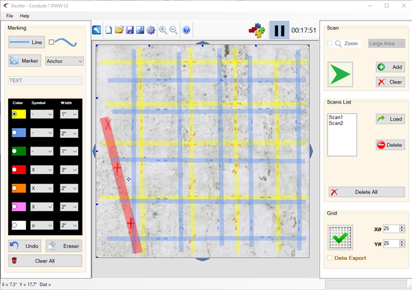
Decifer has been designed to closely resemble the way concrete scanning is done in real life. Simple menus and action buttons will have you scanning in minutes!
Unlimited Practice Patterns
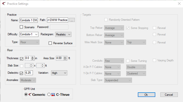
A generated pattern can be restricted to a pre-set level of difficulty or may be user customized. Different kinds of targets can be included in the pattern, with different populating levels for most of them. For example, with top rebar, when “Some Stopping” is checked, there will be at least one top rebar stopping in each direction. For conduits, when “Some Turning” option is checked, there will be at least one turning conduit.
Fast, Realistic Radargrams
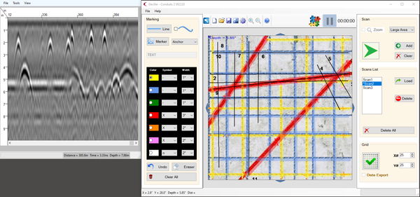
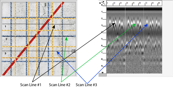
Radargrams are created quickly and realistically corresponding to the scan line selected by the user on the practice pattern. Scan lines can be created anywhere on the pattern and the correct radargram will be generated and displayed!
The radargram is displayed for a selected frequency according to the balance between the resolution and the penetration depth. A signal is built by the simulator based on several parameters, such as:
- The radiation angle: an important factor varying the hyperbolas length.
- Spreading attenuation: the transmitted energy spreads depending on its radiation angle, which causes important signal attenuation.
- Material’s properties: the propagation medium (usually concrete or ground) affects significantly the radargram. The considered material’s properties in Decifer are the dielectric constant (wave velocity) and the loss factor (attenuation).
- Random noise and Anomalies: Can be added to the signal for more realistic radargrams.

Learn to Mark your Results
The marking palette allows for realistic marking using a variety of colors and shapes.
Moving the antenna on the pattern space moves the cursor (dashed vertical line) on the radargram corresponding to the antenna position exactly in the same way as a ground penetrating radar (GPR) antenna with an odometer wheel on a concrete surface. Target positions can then be marked on the scan line with different markers colors and symbols. Various colors and marking symbols may be used to correspond to your own color code standards and scanning methodology. Once sufficient scan lines and target marks have been completed as per your scanning methodology, markings may be connected and target structures drawn by creating straight or curved lines with the same color code.

Check your Work
Unlike training on the job, you can see whether your scanned solution is correct! Scan lines can also be taken on the solution screen to aid in learning to interpret radargrams. To compare markings with the hidden pattern, simply select the solution button to reveal the targets in the slab. The markings made during the scanning process are transparent enough to show the target locations. At this stage, you will also be able to select the type of targets to show, to display their depth at any point, and to use other features to review the practice.

Adjust your Radar Equipment Settings
In the GPR Device window, GPR settings are available to specify signal and radargram characteristics. In the signal settings, check the start time "auto" option to automatically set the 0 time in the radargram to the signal time offset. The samples number can be set to 512, 1024 or 2048. In the antenna settings, the user can set the frequency to be 2.6, 2, 1.6, or 1 GHz. Higher frequency show more resolution but less penetration according to the exponential attenuation law. The number of scans (or signals) per centimeter can be set to 1, 2, 3, or 4, to have different resolution. The internal electronic noise option is recommended for more realistic radargrams.
Save, Practice and Share
Save your work – including the pattern, radargrams and markings. These may be emailed for review by expert trainers to further aid in the training process.
One of the key features of Decifer is the ability to saves practice results for later review. This feature saves the pattern, all scan lines with associated radargrams and markings. The saved file may then be emailed for review by a trainer or used as part of the Decifer Coaching program.
Create and Export 3D Scans
3D grid scans may be created and exported for further practice in processing using other software such as Radan.
Create 3D grid scans for use in external Ground Penetrating Radar processing software (Radan, EKKO_Project, ReflexW, etc.). To start grid scans, check “Grid Scan” in the “Scan” frame to the right of the Pattern Area. Input the desired number of scan lines for the grid in the X direction (left to right) and the Y direction (top to bottom). Click “Run” to start the grid scans. The grid scan lines will be displayed at the end of the process as well as the corresponding radargrams. If the DZT Export option is kept checked, DZT files will be created in the save directory.
